Being, by the nature of my work, very familiar with the production and operation of CP transformer rectifiers (CP TR), I decided to act as an advocate for this equipment type. Without in any way diminishing the merits of modern high-frequency converter technology, I believe that the merits and demand for CP TRs have been unfairly underestimated and the justification for the need to use exclusively switch-mode power supplies (SMPS) rectifiers is far from so clear by my opinion.
The axiom that every coin has two sides, as well as my own observations about these type equipment work, served as the impulse for writing this article. Rather, this is not even an article, but some material for discussion based on the statistical data which I have.
In the Runet, I have seen many reviews and comparisons of CP SMPS, which declare the undeniable advantages of this one over CP TRs. However, when reading these materials, I was constantly haunted by the feeling of incomplete objectivity, and sometimes even some incorrectness in the comparisons of these equipment types characteristics. For example, when comparing the characteristics/properties of an some CP SMPS with a rated power of 1.0 kW with the characteristics of a CP TR with a rated power of 3.0 kW, at a minimum, the weight of these devices should not be compared.
In this regard, I will try to correctly use the data at my disposal as much as possible and avoid using unconfirmed facts. Accented, that I am not a supporter of unambiguous statements and I believe that the principle of variability should be applied to solve each specific solution, i.e. the admissibility of various approaches, methods and ways of solving it. The world is not black and white and there are at least shades of grey. I invite all specialists interested in and involved in this topic to discuss the presented findings and introduce own opinions and promise that not a single question, clarification or comment of yours will remain unanswered.
Before moving on to any comparisons, I would like to draw attention to the fact that in the parts of automation, control electronics and functional capabilities, both types of devices are completely identical. Thus, to a greater extent the comparison will be related to the power part of these device types.
So, let's start with the most common statements and arguments in favor of CP SMPS, declared in various printed and online materials:
1. The SMPS have smaller weight and dimensions compared to transformer ones.
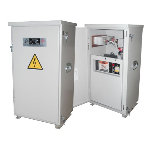
It is partially true statement. The power unit of the CP SMPS has small dimensions and weight per 1 kW of output power. However, an electronic control unit, telemetry equipment, switching electrical harnesses, etc. are required for it as for the CP TRs too. In addition, all this requires an external housing for installation and the ability to protect equipment from unauthorized access and environmental impacts. Thus, at the result we get that the dimensions of theCP SMPS acquire a quite tangible form (500x550x700 mm, 600x450x900 mm, etc.), comparable to the CP TRs, and the weight of the finished device becomes quite noticeable. Depending on the nominal power, the CP SMPS weigh from 50 to 125 kg. For comparison, the CP TRs that I work with directly, with an integrated or external capacitive-inductive filter, have overall dimensions of 440x400x850 mm (440x400x1160 mm when supplied with an external filter unit) and a weight of 65 to 135 kg.
2. The block-modular design of the CP SMPS allows increasing the output power of the rectifier without changing the cabinet, by installing the required number of power modules.
A fair statement, it is a really convenient technical solution. Here, the bureaucratic approval of changes to the design capacity of the CP rectifier will take more time and resources most likely.
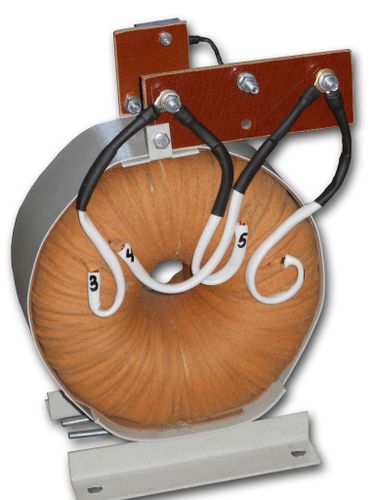
In the CP TRs, achieving such unification is difficult, but not impossible. In particular, the UKZT series CP TRs have a universal design of the external casing, supporting units and a universal output rectifier stage for the power range from 0.3 to 3.0 kW, which allows increasing the power to 3.0 kW by simply replacing the power transformer, which has a cost comparable to the SMPS module of 1 kW. In this case, a spare transformer remains, which can be used to reduce or increase the power of another CP TR. It is also possible to increase the power to 5.0 kW, but technically it will be really more complicated than in the case of an CP SMPS and, possibly, somewhat more expensive. I cannot say for sure, but most likely the same thing can be implemented in the CP TRs of other types.
In fairness, I would like to note that the most attractive feature of the modular design of CP SMPS is the ability to reserve power modules, but this is a question about a slightly different class of equipment.
If we talk about the maintainability of the power section of the CP rectifier, then yes, the SMPS power modules are changed quickly and easily, but the power section of the transformer rectifier can also be repaired in the field in a pair of hours, because the circuitry is very simple, and the element base is accessible. Perhaps it makes sense to compare the cost of a spare power unit of an SMPS power module with the cost of spare parts for repairing a transformer rectifier.
3. The CP SMPSs have a higher quality of structure protection compared to CP TRs, due to the low pulsation coefficient of the output voltage, a wide range of permissible changes in Main voltage and load resistance.
I cannot unconditionally agree with this, since transformer CP TRs equipped with a capacitive-inductive filter provide a output voltage pulsation coefficient comparable to SMPS ones of no more than 3%, and in some cases even 1-2%.
The range of change in supply network voltage, at which CP TRs remain operational, is no less than that of CP SMPSs (from 150 to 264 V AC).
Another informal question: what is meant by the quality of protection of a structure? The quality of protection of a structure is determined by the value and stability of protective potential. As far as I know, DC voltage pulsation does not have a negative effect on the value and stability of the protective potential, since this pulsation does not go into the alternating zone.
As for the range of load resistance, I will have a question to the employees of Clients. In my experience, when working at facilities with some CP SMPSs, I encountered the problem that when it working on a load circuit of less than 1 Ohm, when it was necessary to set a low value of output current (from 1 to 3 A), the CP SMPS behaved unstably. If you allow me, I will not specify the brand of the CP MSPS. When working with CP TRs, I have not encountered such problems, they behaved stably at low-impedance loads of 0.3–0.5 Ohm with a protective current value from 1 A. The question is: is this really true or am I just lucky?
Well, now I will move on to the most interesting and, perhaps, key issue – the significantly higher energy efficiency and, as a consequence, the economic feasibility of the CP SMPSs in comparison with CP TRs.
4. The CP SMPSs have a higher efficiency factor compared to the CP TRs. In addition, the efficiency of the CP TRs drops sharply when the load decreases.
With the correct selection of the LC filter, the efficiency of the CP TRs is comparable to this characteristic of the CP MSPSs in the nominal mode. If there is a difference, it will fall within the range of 1 – 3%.
How true is the statement about a sharp drop in the efficiency of the CP TRs when the load is reduced and what economic losses this entails, let's look further.
Now I will have to provide quite a lot of figures and calculations from the statistical information at my disposal about the operating modes of the CP TRs at real facilities in order to be able to take an analytical look at this issue. I urge all readers who are involved in this topic and have their own statistical information, as well as experience in operating or manufacturing the equipment under discussion. Do not to stand aside and to join the discussion of the topic, express their opinion, agree or disagree with the opinion of author. Looking ahead, I will say that I will use only those characteristics and indicators of the CP SMPSs, manufactured by other companies (not mine), that are presented in the official sources of this companies.
Modeling and comparison of indicators in different operating modes.
To begin with, let's look at the theoretical layout of forces using the example of virtual Switch-Mode and transformer CP rectifiers of some single nominal power, let it be 2.0 kW. Let's compare the total electricity costs for the year and for the regulated service life (15 years).
The power consumption of the CP SMPS with a rated power of 2.0 kW, operating in nominal mode, with an efficiency index of 90%, will be:
per day – 2.0 kW / 0.9 x 24 h. = 53.3 kW*h,
per year – 53.3 kW*h x 365 = 19 454.5 kW*h,
over a service life of 15 years – 19 454.5 kW*h x 15 = 291 817.5 kW*h.
The power consumption of the CP TR with a rated power of 2.0 kW with a LC filter, operating in nominal mode, with an efficiency index of 88%, will be:
per day – 2.0 kW / 0.88 x 24 h. = 54.5 kW*h,
per year – 54.5 kW*h x 365 = 19 892.5 kW*h,
over a service life of 15 years – 19 892.5 kW*h x 15 = 298 387.5 kW*h.
When applying the average electricity tariff of 10,12 RUR per 1 kW*h (for Rostov region, April 2025), we get that the savings on electricity costs in the case of using the CP SMPS will be (19 892,5 - 19 454,5) х 10,12 = 4 432 RUR (about EURO 49) per year or over a 15-year service life - (298 387,5 - 291 817,5) * 10,12 = 66 488 RUR (about EURO 736).
So far, it looks very nice. But we have now considered the case of full load with the maximum efficiency index. You know very well that cathodic protection rectifiers are practically not operated in the nominal power mode in real life, but more on this later. We will "landing" little by little. The efficiency value of cathodic protection rectifiers when operating at an output power mode less than the nominal value is not regulated. However, some manufacturers indicate in the characteristics of CP SMPS an efficiency value of at least 75% when operating at a mode range of 10–20% of the rated power. I admit that the mention of such a percentage of the load is connected with the assumption of a real long-term mode of operation of the rectifiers. I have information about the operation of an CP SMPS rectifier with a nominal power of 2.0 kW, at a real facility, in the operating mode of 8.7% (67V, 2.6A) of the nominal power with an efficiency of 74%.
There is also a test report from an independent laboratory for the UKZT CP TR with an integrated LC filter with a rated power of 2.0 kW, which provided an efficiency of 77.3% when operating in a mode of 9.7% of the rated power.
I will allow myself to assume that the CP SMPS indicated above, when operating in the mode of 9.7% of the nominal power, also will provide a comparable efficiency of 77.3%. Thus, it turns out that, under the specified operating mode, the efficiency of the SMPS and transformer cathodic protection rectifiers are comparable and as result there is no difference in the costs of electrical energy.
And finally, I am getting closer to a more realistic picture of the operating modes of the CP rectifiers (valid for objects in Russia).
While performing maintenance, adjustment and repair work on cathodic protection stations in different regions of the country, I willingly or unwillingly receive quite extensive data on the actual operating modes of cathodic protection rectifiers in different regions of Russia. To obtain an average picture of the operational load of the CP rectifiers, I took data on 411 rectifiers operating in five federal districts: 166 units in the Southern Federal District, 85 units in the Central Federal District, 60 units in the North Caucasian Federal District, 58 units in the Volga Federal District and 42 units in the Ural Federal District. It would have been possible to make a larger sample, but, as you will see, despite the geographical spread, the convergence of the result is high and, assuming that any averaging methods contain a some percentage of error, the difference in results, even if there is one, will not make any significant changes to the overall picture.
Again, let me remind you that the article is potentially of a discussion nature, and if you have alternative information, I will accept it with grateful for discussion, analysis, and, perhaps, to change my point of view.
Well, I'm moving away from the lyrics and to move on to a description of the methodology I used and dry statistical data.
In order to avoid providing a huge number of figures for each of the 411 rectifiers, the average percentage of the working load of a single (“virtual”) CP rectifier in relation to its nominal capacity was calculated for each federal district (See Table 1. Calculation of the average percentage of workload per one CP rectifier).
Table 1. Calculation of the average percentage of workload per one CP rectifier
|
Federal Destrict |
N, pcs. |
Рnom.sum., W |
Рnom.avg., W |
Рout.sum., W |
Рout.avg., W |
Kavg.load, % |
|
SFD |
166 |
247 600 |
1 492 |
9 496 |
57 |
3,83 |
|
CFD |
85 |
142 200 |
1 673 |
1 624 |
19 |
1,14 |
|
NCFD |
60 |
109 000 |
1 817 |
3 156 |
53 |
2,91 |
|
VFD |
58 |
172 200 |
2 968 |
1 565 |
27 |
0,9 |
|
UFD |
42 |
134 200 |
3 195 |
1 110 |
26 |
0,82 |
|
Summary result |
411 |
805 200 |
1 959 |
16 951 |
41 |
2,1 |
The calculations were made as follows:
Рnom.avg. = Р nom.sum. / N
where
Рnom.avg. – is the average nominal power of a single “virtual” CP rectifier,
Р nom.sum. – is the total nominal power of installed CP rectifiers,
N – is the number of CP rectifiers in the sample for calculations;
Рout.avg. = Рout.sum. / N
where
Рout.avg. – is the average power at the output of a single “virtual” CP rectifier,
Рout.sum. – is the total power at the output of the installed CP rectifiers operating in the setting work modes;
Kavg.load = Рout.avg. / Рnom.avg.
where
Kavg.load – is the average percentage of the load of a single CP rectifier in relation to its nominal power.
Thus, from the obtained data, I conclude that the average load of cathodic protection stations, in operating modes, is in the range (I will round off the results) from 1 to 4% of their nominal capacity. If we take the data of the general calculation for all regions, the average percentage of the single rectifier working load is about 2% with an average installed nominal capacity of 1.96 kW. By the way, now I have come to the question of why in the comparison above I used a rectifiers rated power of 2.0 kW.
Well, let's try to calculate the economic indicators of compared two types of cathodic protection rectifiers, based on the results obtained.
Unfortunately, I have very little information on the actual operating modes of CP SMPS from the working objects. However, I have data on the operation of an CP SMPS (2.0 kW), operating in the 1% mode of the nominal power. In this mode, it provides an efficiency of 19%. There are also data on the CP rectifier of the transformer type (2.0 kW) when operating in the mode of 1.5% of the nominal power. In this mode, it provides an efficiency of 45%.
That is, I will again allow myself some assumptions, I hope, without belittling the merits of CP SMPS rectifiers, and my colleagues will not let me make a mistake. If anything, I would be glad to receive your comments and point out any mistakes which I may have made. I would assume that an additional 0.5% (10W) of load on the inverter could double increase its efficiency, from 19 to 38%.
The power consumption of the CP SMPS rectifier with a rated power of 2.0 kW, operating in the mode of 1.5% of the rated power, with an efficiency index of 38% (an assumption due to the lack of a real value of the characteristic), will be:
per day – 2.0 kW x 0.015 / 0.38 x 24 h. = 1.89 kW*h,
per year – 1.89 kW*h x 365 = 689.8 kW*h,
over a service life of 15 years – 689.8 kW*h x 15 = 10 347 kW*h.
The power consumption of the CP TR with a rated power of 2.0 kW with a LC filter, operating in the mode of 1.5% of the rated power, with an efficiency index of 45% (the actual measured value), will be:
per day – 2.0 kW x 0.015 / 0.45 x 24 h. = 1.56 kW*h,
per year – 1.56 kW*h x 365 = 569.4 kW*h,
over a service life of 15 years – 569.4 kW*h x 15 = 8 541 kW*h.
Returning to the calculation of economic efficiency, again using the average electricity tariff of 10.12 rubles per 1 kW*h (according to Rostov region, April 2025), we get that the cost savings, now in the case of using the CP transformer rectifier, will be:
(689.8 – 569.4) x 10.12 = 1,218.4 RUR (about EURO 13.5) per year or for a 15-year service period - (10,347 – 8,541) * 10.12 = 18 277 RUR (about EURO 202).
Thuse, based on the data and calculations provided, I consider the statement “The CP SMPSs have a higher efficiency factor Thus compared to the CP TRs. In addition, the efficiency of the CP TRs drops sharply when the load decreases” to be highly controversial.
According to the rules of writing an article, there should be a section with the important title “Conclusions”, but if you allow me, I will replace it with a section with a different title – “Questions”.
First question. I have a fix feeling that the costs of maintenance and repair of the SMPS type rectifiers are somewhat higher than those of transformer-type rectifiers. This may be due to both the element base of the rectifiers and the required qualifications of higher-level staff, due to a significant difference in the complexity of the rectifiers circuitry of these types. Not having experience in servicing CP SMPS rectifiers on a permanent basis, I cannot assess the level and composition of these costs objectively. For my part, I would be very grateful if someone could share their experience and knowledge in this area. Now, the question is this: It is unlikely, but let us assume that the operating costs of transformer and SMPS rectifiers are comparable, but the initial cost of last is obviously higher. Is this difference of initial costs offset by possible savings on energy consumption?
The second question follows from the first. When taking into account economic performance indicators, isn't it worthwhile to comprehensively evaluate the parameters and aspects related to the operation and life cycle of the equipment to obtain a real picture, and not just pretty numbers taken out of context?
No. Still, I will allow myself to make a small conclusion, or rather, express my subjective opinion.
In my opinion, in modern life, rectifiers of both types should be presented, and the choice for the use of one or another type should be determined by a comprehensive assessment of the conditions of the planned operation of the purchased equipment in order to achieve a real economic effect. The list of these conditions must include not only the planned percentage of long-term load, but also the climatic conditions of a specific region, the quality of power supply, the configuration of the electrochemical protection system, a real assessment of the staff qualification level and, probably, many other factors that are better known to operating services and organizations based on their experience.
Assessing the above information, the main question indicated in the title of the article comes to mind: Are the advantages of the сathodic protection rectifiers based on Switch-Mode power suppliers (CP SMPS) over transformer ones so clear? Is it too early to exclude from life the latters?
I will stop here and will be grateful to all colleagues for participating in the discussion of the identified theme in an open dialogue mode.


