Controllers of the KATRON series are an universal microprocessor device designed for building control and information systems for automation of technological processes as measuring electrical quantities either directly or by connecting external sensors, monitoring and controlling DC sources and other electronic devices, to transmitt measured values and receiving of control commands via GSM-communication channels and wired lines.
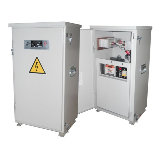
The KATRON-SKZ controller modification is programmed to monitor and control the electrochemical protection equipment (cathodic protection and drainage protection rectifiers) and is a more advanced modification of the controllers KATRON-1 and UNIKONT-SKZ manufactured till 2011. At present, the KATRON-SKZ controllers installs in the Don-TM and UKZT-TM cathodic protection rectifiers.Also for the integration of CP equipment into the DON-STEL-K or similar telemechanics system, they can installed on the some others cathodic protection rectifiers as an additional module, for realization the function of parameters monitoring, and of the function remote control.
The controller is equipped with a digital display that allows you to visualize the measured values and service data. The basic software of the controller allows the end user to independently program the modes of operation of the CP rectifier both remotely and by entering commands from the built-in keyboard.
For using functions of the remote monitoring of control it is possible to use specially STEL-K terminal software or of some SCADA systems.
Standard functions of the KATRON-SKZ controller for the cathodic protection rectifiers.
Measured and transmitted by the controller through the telemechanics system channels next values and signals from the CP rectifier:
- Output voltage DC - 0...99,9 V
- Output current DC - 0...99,9 A
- Protective potential voltage (reference electrode (CuSO4) is neded) - 0,5...4,9 V
- Time counter of full work - 0...999999,9 h
- Time counter of protection - 0...999999,9 h
- Electricity meter readings and the Main voltage AC (when connecting an appropriate type of electricity meter)
- Alarm transmission to the telemechanics system terminal and signal duplication via SMS to the staff’s mobile phone (up to 4 phone numbers are possible)
- Transmitting the archive of the CP rectifier electronic journal of work (the controller save the journal of the 2 month period with 1 hour step for basic values)
The controller equipped by built-in GSM/GPRS cellular communication module. This module is 900/1800 MHz dual-band GSM/GPRS modem and provides for the exchange of information between the control center and the controller via data (CSD) and SMS channels. The current state of the module is displayed by a GSM LED.
Controller's keyboard
The keyboard of the controller is designed for changes, viewing and entering the main current parameters and operating modes of the CP rectifier or some DC source. The keyboard has seven keys (five for main manipulation and two for some additional functions whicth may programmed).
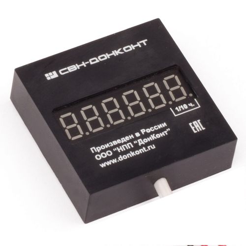
Digital six-digit seven-segment LED indicator
The LED indicator is used to display information about the value of the measured values and the current state of the controller, as well for visualisation of entering control commands.
Real time clock
The built-in real time clock ensures synchronization of the controller operation algorithms with the current time. They count time with leap years up to 2100. The clock circuit is non-volatile; its power supply in case of absence of external voltage is provided by a special backup battery.
Non-volatile memory EEPROM
The controller provides for maintaining an archive of the main parameters measured by the controller. These include current, voltage, protective potential (high-resistance measuring DC voltage input), DC power, total power consumed, hours of operation in the protection mode, and the temperature inside the controller. Records are kept in the form of a cyclic archive with a total number of records up to 1440 (average hourly values for 60 days). Parameters are read remotely from a personal computer equipped with a GSM / GPRS modem and special software..
Temperature sensor
The digital temperature sensor is integrated into the microcontroller, it allows to control the temperature inside the controller in the range from -40 to 99 ° C.
Input to connect the primary power source
The input for connecting the primary AC power source with a voltage of 8–15 V to the controller is intended to ensure its operation in the main mode.
External battery input
The input for connecting an external battery to the controller is designed to ensure its uninterrupted operation in case of loss of Main AC. The controller disables unused peripherals, stops maintaining archive records, and goes into low power mode. This allows you to significantly increase the operating time of the controller when powered by battery. An external sign of the lack of primary power is a burning point in the lower right corner of the indicator. The battery starts charging automatically when the primary power is turned on.
Analog-to-digital converter controller
The controller’s analog-to-digital converter provides a resolution of 17 bits in the range from 0 to 1.55 V. Devices with a voltage output can be connected to the analog inputs (see Table 1). Conversion factors, signal limit levels are determined by the manufacturer for each input.
Table 1
| Analog inputs |
Name of parameter |
|||
|---|---|---|---|---|
|
|
Output |
Output |
Protective |
|
|
Differential input |
Yes |
No |
Yes |
|
|
Voltage range on |
0-0.075 |
0-100 |
0-5 |
|
Current DC analog measurement input
The analog current DC measurement input of the controller is intended for measure the drop voltage on a measuring shunt (75 mV, 100 A) in the range from 0 to 75 mV and calculate to current Amps.
Voltage DC analog measurement input
Analog input measuring the DC voltage at the output of the power supply.
The output voltage of the power source, as measured by the controller, is in the range from 0 to 100 V.
Analog input of protective potential measurement (voltage from an external DC source)
Analog input of protection potential measurement is designed to connect an external potential sensor. A feature of this input is a large input resistance, not less than 10 MΩ. The range of the potential measured by the controller is from 0 V to -5 V.
Also the controller has additional inputs and outputs listed below
Discrete inputs of the corrosion rate sensor (external sensors of the “dry contact” type with the common wire)
Pulse-counting input
Discrete input for selection of channel CAN/GSM
Input for connecting the alarm sensor
Galvanic untied two-wire general-purpose input
Galvanic untied four-wire output for connection to the thyristors (SCR) of bridge rectifier
Galvanic untied two-wire general-purpose output


